Overview
| Information | 5V, Single Chip WAN Multi-Mode Serial Transceiver |
|---|---|
| Supported Protocols | RS232, RS449, EIA530, V.10, V.11, V.28, V.35, V.36, X.21 |
| Supply Voltage (Nom) (V) | 5 |
| No. of Tx | 7 |
| No. of Rx | 7 |
| Data Rate (Mbps) | 16 |
| HBM ESD (kV) | 2 |
| Internal Termination | V.35, V.11 |
| VL Pin | |
| Temperature Range (°C) | 0 to 70 |
| Package | LQFP-80 |
The SP506 is a monolithic IC that supports eight (8) popular serial interface standards for DTE to DCE connectivity. The SP506 is pin-to-pin compatible to our SP505 multi-protocol transceiver but with faster throughput. The seven (7) drivers and seven (7) receivers can transmit and receive signals at 20Mbps. As with the SP505, the SP506 requires no additional external components for compliant operation for all of the eight (8) modes of operation. All necessary termination is integrated within the SP506 and is switchable when V.35 drivers, V.35 receivers, and V.11 receivers are used. The SP506 can operate as either a DTE or DCE.
Additional features with the SP506 include internal loopback that can be initiated in either singleended or differential modes. While in loopback mode, driver outputs are internally connected to receiver inputs creating an internal signal path convenient for diagnostic testing. This eliminates the need for an external loopback plug. The SP506 also includes a latch enable pin with the driver and receiver address decoder. Tri-state ability for the driver and receiver outputs is controlled by supplying a 4-bit word into the address decoder. Seven (7) drivers and one (1) receiver in the SP506 include separate enable pins for added convenience.
- Interface Modes Supported:
- RS-232 (V.28)
- X.21/RS-422 (V.11)
- EIA-530 (V.10 & V.11)
- EIA-530A (V.10 & V.11)
- RS-449 (V.10 & V.11
- V.35 (V.35 & V.28)
- V.36 (V.10 & V.11)
- RS-485 (unterminated V.11)
- Software Selectable Protocol
- Highest Differential Transmission Rates at over 20Mbps
- +5V Only Operation
- Seven (7) Drivers and Seven (7) Receivers
- Driver and Receiver Tri-state Control
- Internal Transceiver Termination Resistors for V.11 and V.35 Protocols
- Loopback Self-Test Mode
- Improved ESD Tolerance for Analog I/Os
- Compliant to NET1/2 and TBR2 Physical Layer Requirements
- Used in WAN Serial Ports in Routers, Switches, DSU/CSU's and other Access Devices
Documentation & Design Tools
| Type | Title | Version | Date | File Size |
|---|---|---|---|---|
| Data Sheets | SP506 5V Single Chip WAN Multi-Mode Serial Transceiver | 1.0.1 | August 2010 | 1.4 MB |
| Application Notes | Advantages of Designing with Multi-Protocol Transceivers Application Note | R00 | September 2023 | 2.5 MB |
| Application Notes | RS-232 and RS-485 PCB Layout Application Note | R00 | December 2022 | 2.8 MB |
| Application Notes | AN218, SP50x RS-232 Latch-up Prevention | April 2013 | 178.8 KB | |
| Application Notes | ANI-14, DTE and DCE Terminology Explained | B | December 2006 | 25.4 KB |
| Application Notes | ANI-17, Multiprotocol DTE and DCE Options | B | December 2006 | 34.6 KB |
| Application Notes | ANI-16, Design Guide for Multi-Protocol Serial Ports | A | November 2005 | 462.9 KB |
| Design Solutions | DS-27, Signal Routing Considerations for 80-Pin Multiprotocol Communications Interface Devices | November 2007 | 246.6 KB | |
| Product Brochures | Interface Brochure | November 2023 | 3.7 MB |
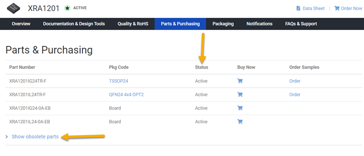
Parts & Purchasing
| Part Number | Pkg Code | Min Temp | Max Temp | Status | Suggested Replacement | PDN |
|---|---|---|---|---|---|---|
| SP506CF | MQFP80 | 0 | 70 | OBS | ||
| SP506CF-L | MQFP80 | 0 | 70 | OBS | ||
| SP506CM-L | LQFP80 14x14 | 0 | 70 | OBS |
Active - the part is released for sale, standard product.
EOL (End of Life) - the part is no longer being manufactured, there may or may not be inventory still in stock.
CF (Contact Factory) - the part is still active but customers should check with the factory for availability. Longer lead-times may apply.
PRE (Pre-introduction) - the part has not been introduced or the part number is an early version available for sample only.
OBS (Obsolete) - the part is no longer being manufactured and may not be ordered.
NRND (Not Recommended for New Designs) - the part is not recommended for new designs.
Packaging
Notifications
FAQs & Support
Search our list of FAQs for answers to common technical questions.
For material content, environmental, quality and reliability questions review the Quality tab or visit our Quality page.
For ordering information and general customer service visit our Contact Us page.
Submit a Technical Support Question As a New Question
The Parts & Purchasing section of the product page shows the Status of all orderable part numbers for that product. Click Show obsolete parts, to see all EOL or OBS products.