SP3224E
Overview
| Information | Intelligent +3.0V to +5.5V RS-232 Transceiver with Auto On-Line® Plus |
|---|---|
| Supply Voltage (Nom) (V) | 3.3, 5 |
| No. of Tx | 2 |
| No. of Rx | 2 |
| Data Rate (kbps) | 250 |
| HBM ESD (kV) | 15 |
| IEC 61000-4-2 Contact (±kV) | 8 |
| Int. Charge Pump | ✔ |
| No. of Ext Caps | 4 |
| Nom Cap Value (µF) | 0.1 |
| Shutdown | ✔ |
| Internal Caps | |
| TTL Tri-State | ✔ |
| Auto On-Line | ✔ |
| VL Pin | |
| Temperature Range (°C) | 0 to 70, -40 to 85 |
| Package | TSSOP-20, SSOP-20 |
The SP3224E/3225E are 2-driver/2-receiver devices and the
SP3226E/SP3227E are 1- driver/1-receiver devices. All are ideal for
computer peripherals, point-of-sale equipment, consumer and embedded
applications. These devices use an internal high-efficiency, charge-pump
power supply that requires only 0.1μF capacitors in 3.3V operation.
This charge pump and MaxLinear’s driver architecture allow it to deliver
compliant RS-232 performance from a single power supply ranging from
+3.0V to +5.5V. At voltages between 2.7V and 3.0V the driver outputs are
compliant with RS-562 and can interface to RS-232 over short cables.
The Auto On-line down state upon detecting activity and to enter a low
power shutdown if idle. This power saving feature functions without
system intervention or modifications to software or drivers.
- 2-driver, 2-receiver RS-232 transceiver
- Enhanced power savings compared to SP3223 type devices
- 250kbps slew-limited data rate
- Auto Online Plus™ automatically puts device into 1μA shutdown mode if Tx Inputs and Rx Inputs are idle for 30 seconds
- Device re-awakes on bus activity
- No control inputs or software driver changes required
- Meets true EIA/TIA-232-F requirements from a +3.0V to +5.5V power supply
- Regulated Charge Pump for stable outputs regardless of Vcc variations
- Upgradeable to SP3225E for 1Mbps high-speed serial
- ESD Specifications:
- ±15KV Human Body Model
- ±8KV IEC1000-4-2 Contact Discharge
- Diagnostic/Serial ports on embedded applications
- Handheld Test Equipment
- PC related Peripherals and Equipment
- Battery Powered Equipment
- Point-of-sale Equipment
- Set-top Box
Documentation & Design Tools
| Type | Title | Version | Date | File Size |
|---|---|---|---|---|
| Data Sheets | SP3224E-SP3227E 3.0V to 5.5V RS-232 Transceivers with Auto On-Line® Plus | 1.0.1 | August 2011 | 4.2 MB |
| Application Notes | RS-232 and RS-485 PCB Layout Application Note | R00 | December 2022 | 2.8 MB |
| Product Brochures | Interface Brochure | November 2023 | 3.7 MB |
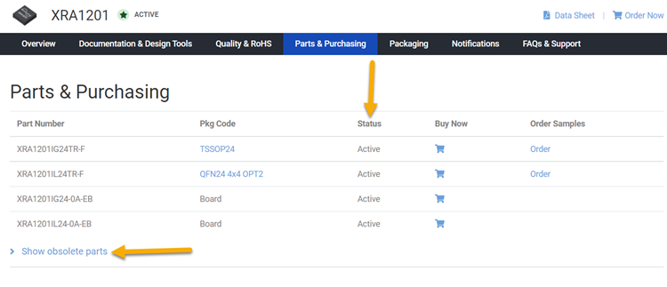
Parts & Purchasing
| Part Number | Pkg Code | Min Temp | Max Temp | Status | Suggested Replacement | PDN |
|---|---|---|---|---|---|---|
| SP3224ECA-L | SSOP20 | 0 | 70 | OBS | SP3224EEY-L/TR | |
| SP3224ECA-L/TR | SSOP20 | 0 | 70 | OBS | SP3224EEY-L/TR | |
| SP3224ECY-L | TSSOP20 | 0 | 70 | OBS | SP3224EEY-L/TR | |
| SP3224ECY-L/TR | TSSOP20 | 0 | 70 | OBS | SP3224EEY-L/TR | |
| SP3224EEA-L | SSOP20 | -40 | 85 | OBS | ||
| SP3224EEA-L/TR | SSOP20 | -40 | 85 | OBS | ||
| SP3224EEY-L | TSSOP20 | -40 | 85 | OBS | SP3224EEY-L/TR | |
| SP3224EEY-L/TR | TSSOP20 | -40 | 85 | OBS |
Active - the part is released for sale, standard product.
EOL (End of Life) - the part is no longer being manufactured, there may or may not be inventory still in stock.
CF (Contact Factory) - the part is still active but customers should check with the factory for availability. Longer lead-times may apply.
PRE (Pre-introduction) - the part has not been introduced or the part number is an early version available for sample only.
OBS (Obsolete) - the part is no longer being manufactured and may not be ordered.
NRND (Not Recommended for New Designs) - the part is not recommended for new designs.
Packaging
Notifications
FAQs & Support
Search our list of FAQs for answers to common technical questions.
For material content, environmental, quality and reliability questions review the Quality tab or visit our Quality page.
For ordering information and general customer service visit our Contact Us page.
Submit a Technical Support Question As a New Question
For RS-232 it is 50 feet (15 meters), or the cable length equal to a capacitance of 2500 pF, at a maximum transmission rate of 19.2kbps. When we reduce the baud rate, it allows for longer cable length. For Example:
| Baud Rate (bps) | Maximum RS-232 Cable Length (ft) |
| 19200 | 50 |
| 9600 | 500 |
| 4800 | 1000 |
| 2400 | 3000 |

The Parts & Purchasing section of the product page shows the Status of all orderable part numbers for that product. Click Show obsolete parts, to see all EOL or OBS products.