
MaxAITM Use Case Aware
AI/ML Framework
Enhances Overall Wi-Fi Experience
and Lowers Costs for MSOs


Sierra
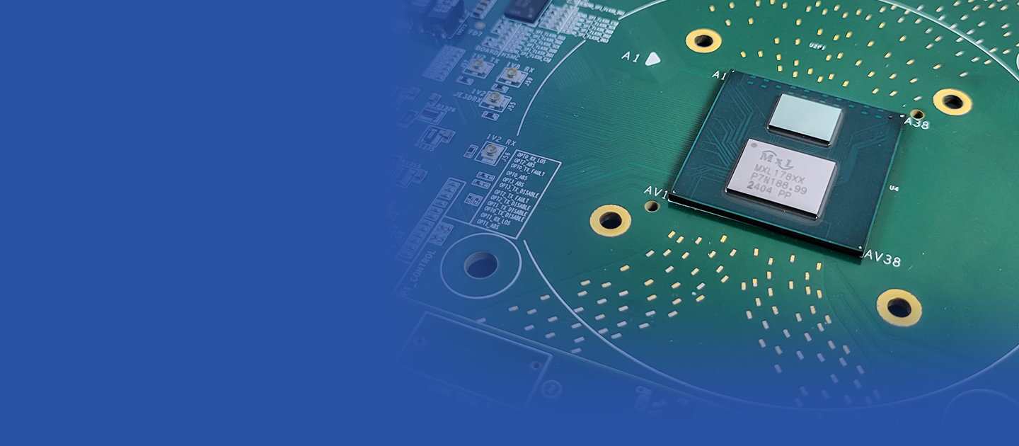
Single-chip O-RAN platform for macro,
massive MIMO, picocell, and all-in-one
small cells radio units.
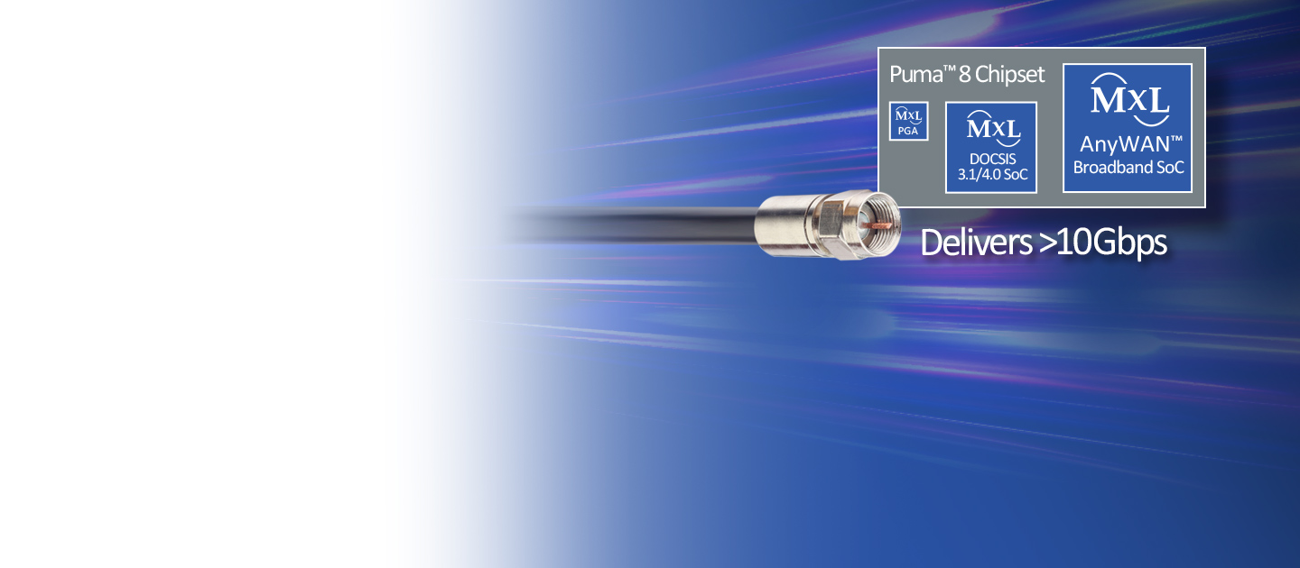
Puma™ 8
DOCSIS® 4.0 ESD/FDD
Achieves Over 10Gbps Throughput
Offering Cable Service Providers
Maximun Network Upgrade Flexibility
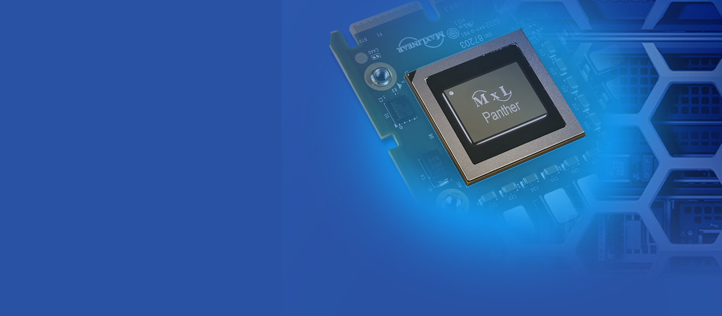
MaxLinear and Dell
New Collaboration to Drive Mission Critical
Workload Performance in Next-Gen Enterprise
and Cloud Storage Systems
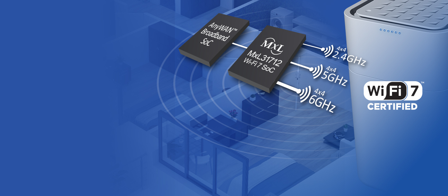
AnyWAN™
Brings Fully Converged Access
Platform with Unprecedented
Scalability to Home Gateway Design

We Enable Multi-Gig Connectivity in Diversified Markets

Access
Solutions that bring 10Gbps to the home over copper, coax, and fiber

Connectivity
Wired and wireless solutions that deliver up to 10Gbps throughout the home

Industrial
Power Management, Interface, and G.hn solutions that address industrial and multi-market applications
Power Management
Interface

Infrastructure
4G/5G wireless, enterprise server/storage, 400Gbps optical and multi-gigabit wireline communication network solutions
Join Our Team
Maximize Your Potential
Join the MaxLinear team and help shape the future of networking and communications technology

Our Latest


